Understanding Computer Networks
Demystifying the basics of computer networks: A beginner's guide to understand how devices communicate


What is a computer network?
The basic explanation for this question is that it is a collection of interconnected devices and computers that can communicate and exchange data.
And what is the internet?
The Internet is a global network of interconnected computers and servers that allows people to communicate, share information, and access services and resources anywhere. (The entire connection of these computers on a global scale is called the internet)
The origin story of computer networks
The ARPANET
The U.S. Department of Defense's Advanced Research Projects Agency (ARPA) launched the creation of a computer network that could link geographically separated research institutes and universities in the late 1960s, which is where computer networks got their start.
ARPA had facilities and infrastructure buildings where they would do their research. But the only problem was that those locations were far apart from each other and they had no clue how to communicate with each other. This is where ARPANET came into existence.
The ARPANET, a predecessor to today's Internet, was created to make it possible for academics to share computing resources and communicate over vast distances. The ARPANET expanded over time, linking more institutions and ultimately developing into the worldwide network we know today.
The ARPA of the US Department of Defense built one of the first computer networks, known as ARPANET, in the late 1960s. The network was created to link academic institutions and research centers engaged in defense-related projects.
The Stanford Research Institute (SRI), the University of Utah, the University of California, Santa Barbara (UCSB), and the University of California, Los Angeles (UCLA) were the first four universities connected by the network. The Massachusetts Institute of Technology (MIT), the University of Illinois, and the RAND Corporation are a few of the colleges and research centers that have joined the network over time. The network expanded quickly and eventually developed into the core of the current Internet.
The ARPANET was able to transmit and receive data using certain protocols (rules). Since data can be of various types like texts, emails, videos, music, voices, and images, different protocols were needed out of which TCP/IP was one of them.
Referencing documents
Since ARPANET was initially a research-based project, there was no established method for citing documents from other publications. Instead, academics and programmers used ad hoc techniques to reference materials, such as manually entering the whole location of the document or utilizing numeric identifiers.
But as the network expanded and the number of documents made available there rose as well, it became obvious that a more uniform system for referencing documents was required. The Uniform Resource Locator (URL), a brand-new system for referring documents, was put forth in 1973 by a researcher by the name of Vint Cerf.
A consistent method of referencing documents on the network was offered via the URL protocol. The protocol (such as http or ftp), the domain name or IP address of the server hosting the document, and the route to the document on the server are all components of a URL. A URL for a file stored on the UCLA server would resemble this, for instance: http://www.ucla.edu/docs/mydocument.html.
ARPANET adopted the URL protocol, and it subsequently became the norm for referring documents on the Internet. Today, URLs are a crucial component of the World Wide Web, allowing users to access millions of files and resources stored on servers around the globe.
The World Wide Web
Web browsers are used to access the World Wide Web (WWW or the Web), which is a collection of connected publications and resources, over the Internet. All of the website resources are stored on servers.
British computer scientist Tim Berners-Lee developed it in 1989 while he was employed by the European Organization for Nuclear Research (CERN) in Switzerland.
The Internet, a vast network of connected computer networks, is the foundation upon which the Web is created. Web users can access and interact with documents and resources (such as photographs, videos, and apps) through a graphical user interface using web browsers, in contrast to other internet-based services like email and file sharing.
A mix of HTML (Hypertext Markup Language) for content organization, CSS (Cascading Style Sheets) for presentation and JavaScript for interactivity is used to build the millions of web pages that make up the Internet. Users can access a variety of materials and travel across pages thanks to the hyperlinks connecting these pages.
Today, the Internet is a vital component of life for billions of people all over the world. It has fundamentally changed how we interact with one another, get information, conduct business, receive education, and enjoy ourselves.
World's first website
Tim Berners-Lee developed the first website in the history of the Internet in August 1991. The website's objective was to provide details about the World Wide Web project and how to access it. It was hosted on Berners-Lee's NeXT computer at CERN.
By today's standards, the website was fairly simple, consisting of a single page with plain text and a few hyperlinks. The page explained what the World Wide Web was, how to utilize web browsers, and how to set up a web server.
Back then, this is how it looked like..
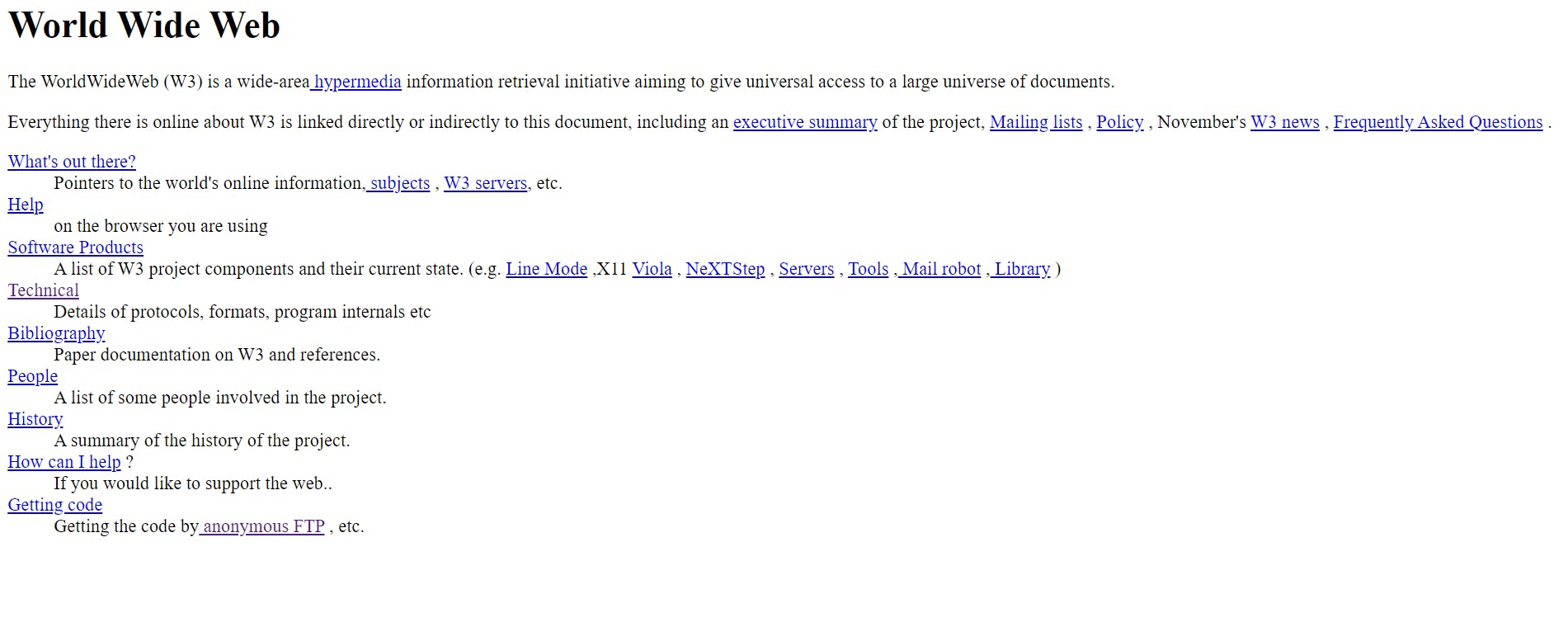
The first website's URL was http://info.cern.ch/hypertext/WWW/TheProject.html. The website is still accessible as an archived copy today, and you can view it to see what the first website on the Internet looked like. You can get the hang of it by going to the website and trying out the links.
Now for the core of the topic!
Overview of client-server architecture
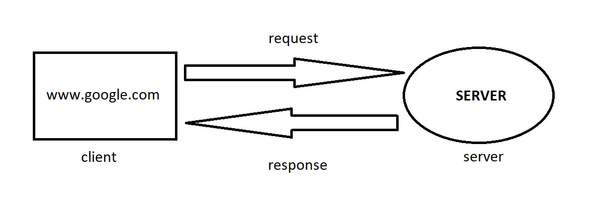
Let's take an example from our daily lives.
Whenever we type google.com from our computer or say we want to look up for something on Google, unknowingly we send a request to a server (another computer) saying we need these many resources. This server, which is located far away from us, sends us a response in the form of web pages.
Protocols
Now computers don't just communicate with each other right away without any underlying rules. Data transmission needs some set of protocols otherwise, everyone with their own rules will create a messed up situation, isn't it?
For general information, the Internet Society has made these rules.
Some of the protocols are :
TCP (Transmission Control Protocol)
Data is transmitted without any frame drop (No data is lost), ex: emails, messages, etc.
UDP (User Datagram Protocol)
Some data may be lost during the transmission and it doesn't matter.
ex: video conferencing, gaming, etc.
HTTP (Hyper Text Transfer Protocol)
This protocol is used by WWW. It defines some set of rules for sending web pages along with some required resources between client and server, back and forth.
There are some more that we are going to learn along the way!
How data is transferred?
Data as we know it, doesn't travel in one go, instead it is transmitted in small chunks. Be it watching movies online or loading web pages, data is always received in packets.
Now when we type google.com, how does it know which server to request?
Every website is linked with an IP address where it is located in a particular server. Also, every computer is registered with an IP address when they take internet service for the very first time.
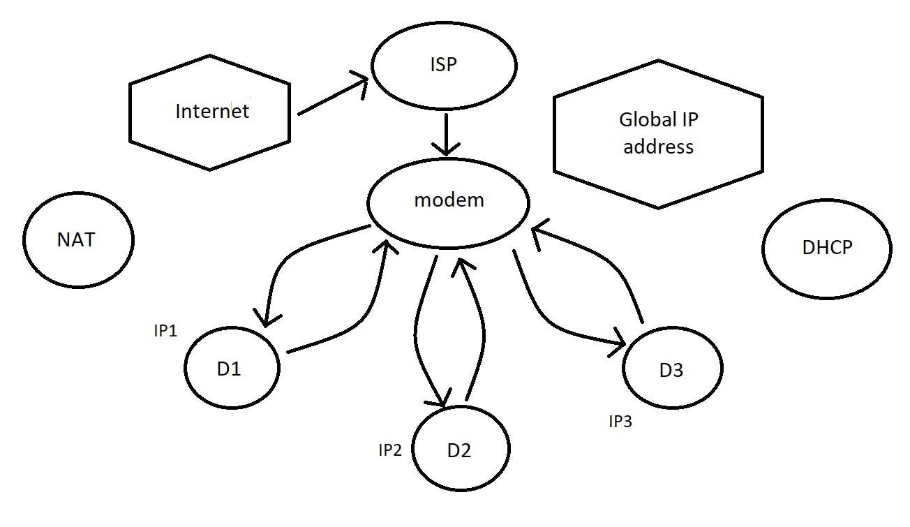
Let's say, I am connected to the Internet with the help of an Internet Service Provider (ISP). It provides me with a modem or a router. It has a global IP address. And there are (say) 3 devices connected to the wifi. The modem assigns an IP address to each of these devices using the DHCP protocol. These are called local IP addresses.
Device D1 makes a request to Google. It is then forwarded by the modem to the Google server. Once when ready, it sends back the response with the required results to the global IP address of the modem. The modem in turn knows that device D1 had sent the request earlier. So now it sends back the results to D1 using NAT (Network Access Translator).
But how does the modem know which application in the device is requesting data? It is because there can be many internet applications or browsers requesting. There is something called a Port Number. It determines which application the data needs to be fed into.
To summarize, the IP address identifies the computer, whereas, the port number identifies the application.
Port Numbers
These are communication endpoints that allow a specific program or an application service to send or receive data.
A port number has 16 bits, each of which can either be 0 or 1. The total numbers that can be created are 2^16 = 65535.
HTTP uses port 80 for communication back and forth between the client and server computers. Similarly, mongo DB uses port 27017.
Ports varying from 0 - 1023 are called reserved ports, ex: HTTP. Whereas ports from 1024 - 49152 are reserved for applications like SQL: 1433. The remaining ones can be used for personal use.
(More on ports ahead..)
Internet connectivity
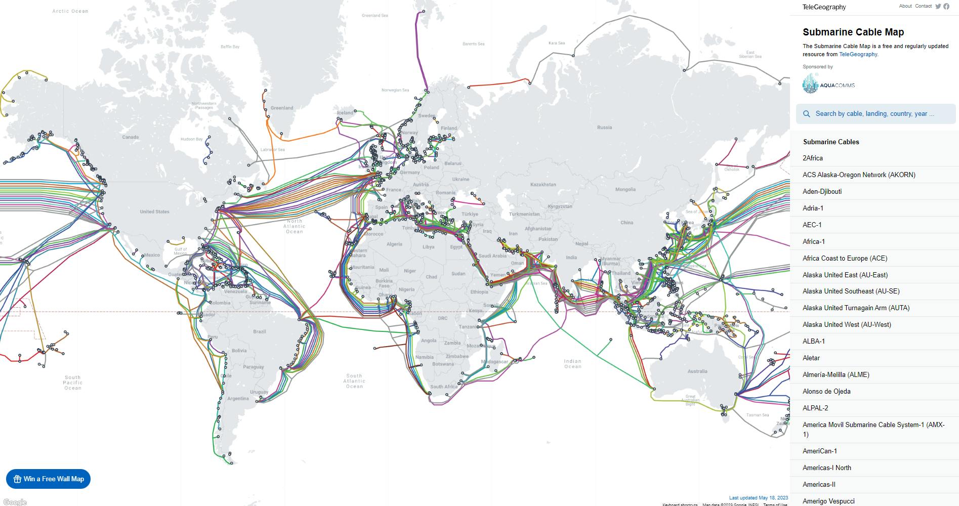
There are optical fiber cables that stretch across continents underwater. These are buried deep inside water and are guarded well enough to survive the high pressure of the water. It is the main reason why we have high-speed internet. The above image is from the submarine cable map.
Basic terminologies
LAN - Local Area Network. This is a type of network that is restricted to a small geographic area like houses, or offices. There can be thousands of computers connected in that area. These computers can be connected using ethernet cables, WIFI, etc.
WLAN - Wireless Local Area Network. This network is a type of LAN that connects devices within a local area wirelessly such as your laptops, cell phones, etc.
MAN - Metropolitan Area Network. This network stretches across cities covering even a larger area than LAN but is smaller than WAN.
WAN - Wide Area Network. This network covers a vast area connecting countries and cities using optical fibre cables.
The Internet is a collection of all the above networks. A lot of LANs are connected using MANs that are again connected using WANs.
Modem - (short for modulator-demodulator) - It is a device that is used to convert digital signals to analog signals and vice-versa for transmission over communication lines such as cable or telephone lines. A modem enables computers within a network to connect and communicate with the Internet through the Internet Service Provider.
Router - It is a device that routes or directs data packets based on their IP addresses to different devices within home or work office networks. Acting as a central hub, it assigns unique local IP addresses to devices. Routers use Network Address Translation (NAT) to allow multiple devices to share a single public IP address provided by the ISP.
Computers are connected using some basic topologies as follows -
- Point-to-point topology - Here nodes or computers are directly connected to each other. It provides the simplest communication between two nodes.
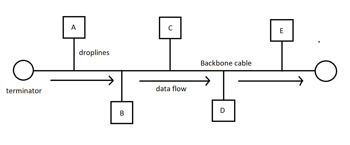
- Bus topology - Here the computers are connected to a single long cord/cable using droplines. It is a multi-point connection and one-directional. At any given time, only one computer communicates with the other. The cable is also called the backbone. If it breaks, every computer loses its connection with the others. Hence it is not robust. But if one node breaks, it doesn't affect the others.
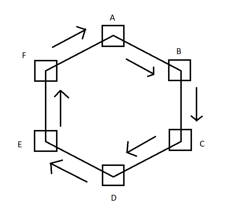
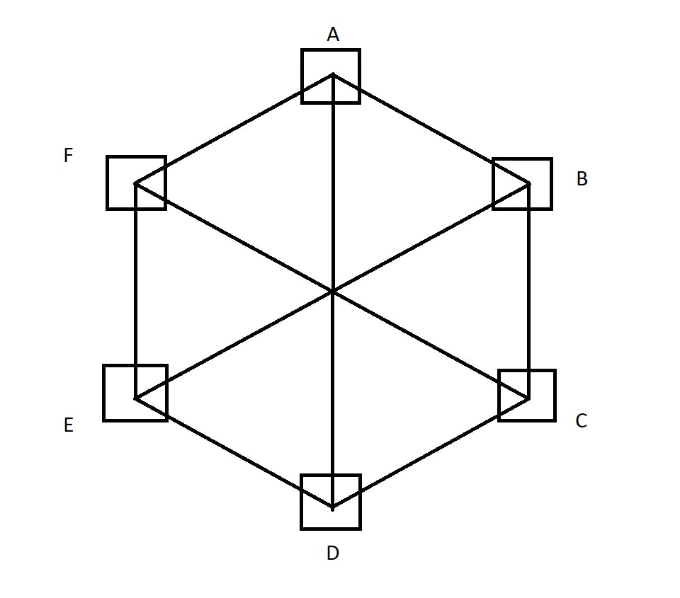
- Ring topology - Here the computers are connected in the form of a ring-like structure. In the given image, if A wants to communicate with D, it has to travel through B and C unnecessarily. If there is a breakage anywhere in the ring, there is no connection among them.
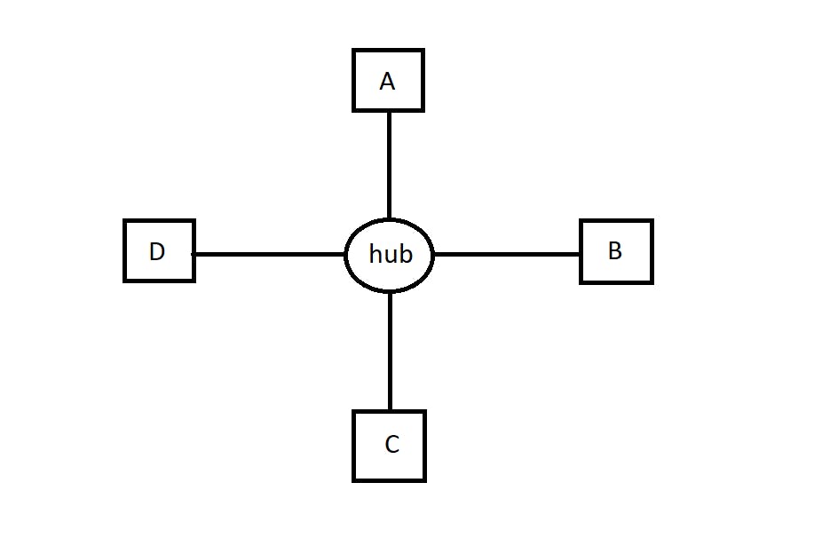
Star topology - Here the computers are connected to a central device or a hub.
Any computer can communicate with the other directly through the hub. But if the hub goes down, the connection fails.
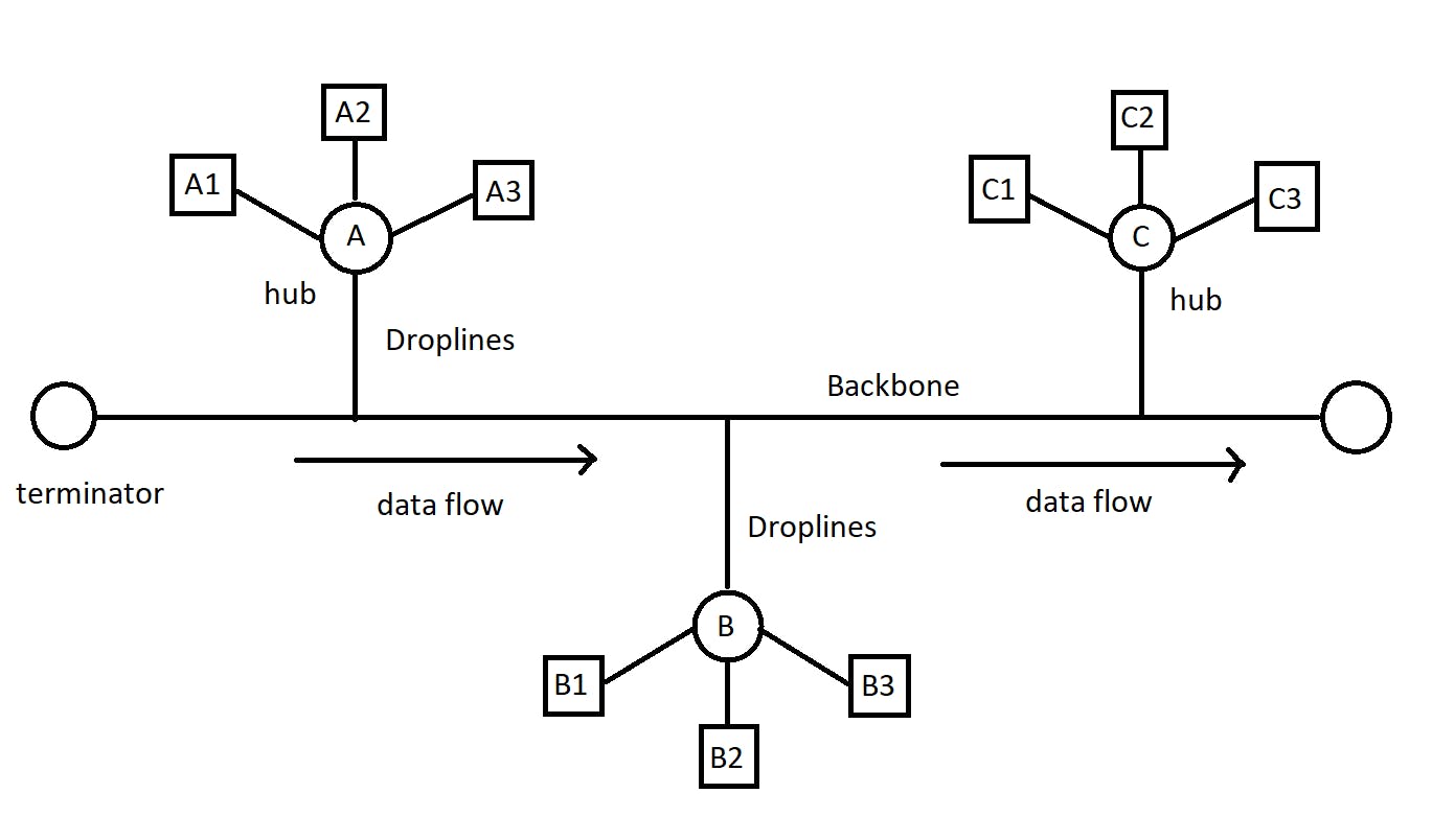
- Tree topology - It is a combination of bus and star topology. All the computers are connected point-to-point with the hub. And the hub is connected to the cable.
- Mesh topology - Here, each and every computer is connected point-to-point to every single computer. It is expensive as too many wires are used. If a new computer needs to be installed, care has to be taken as it will have to be connected to all the computers.
Structure of Network -
To understand the structure of a network, let's take a real-world example :
Let's say you order a product that exists in the US, on Amazon. That product is shipped by some company in the US from the Amazon warehouse. It is then transported to your country. It is fetched by Amazon in your country followed by delivery of the product. At the end of the day, you receive it.
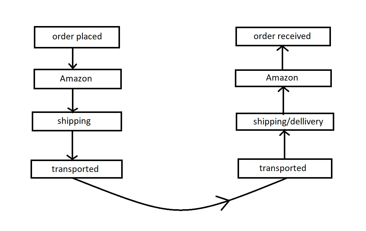
The Internet is just like that!
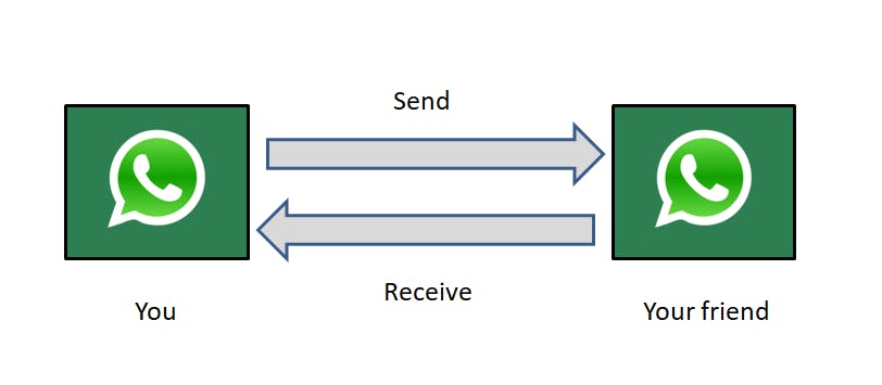
While texting on (say) Whatsapp (application), we send and receive text messages. But we don't know the underlying architecture of how it happens (like how the messages literally travel to the receiver). Let's look into it!
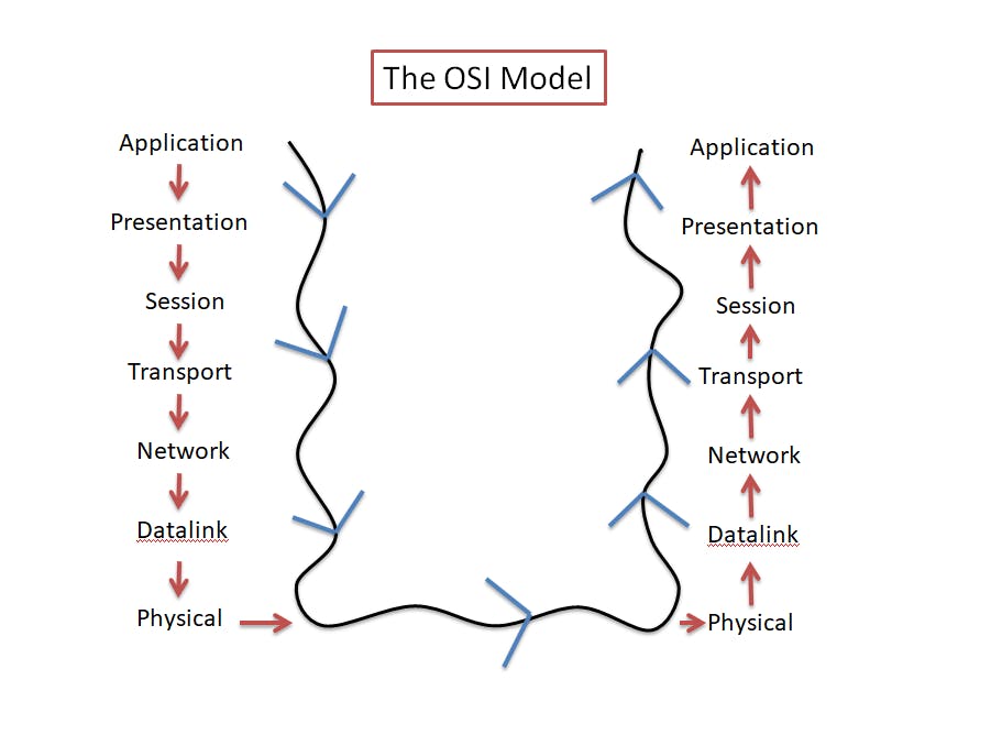
The OSI Model and the TCP/IP Model
OSI stands for Open System Interconnection Model. It is a standard made for computers on how to communicate with each other. There are 7 layers in the OSI model:-
Application
Presentation
Session
Transport
Network
Data link
Physical
The TCP/IP (Transmission Control Protocol / Internet Protocol) model is a more practical model that is primarily used by computers these days. The OSI model is the foundational concept on which TCP/IP is based. Here the application layer includes itself, presentation, and session layers. The network access layer includes the Data link layer and the Physical layer. Hence, it comprises only 4 layers.
Application
Transport
Network
Network Access
Let's look into these layers in detail.
The Application layer
It is the 7th layer of the OSI model.
It is implemented in software.
The apps we use daily like WhatsApp, Twitter, Gmail, Facebook, Instagram, browsers, etc. lie in the application layer.
It provides services to end-user applications.
It is the first or the last point of contact between the users and computers.
The protocols that enable applications to communicate with each other are HTTP, FTP, SMTP, PIP, POP, IMAP, DNS, SSH, etc.
The application layer is responsible for providing an interface between the user and the network. It enables the user to access and use the network.
Let's take the example of WhatsApp,
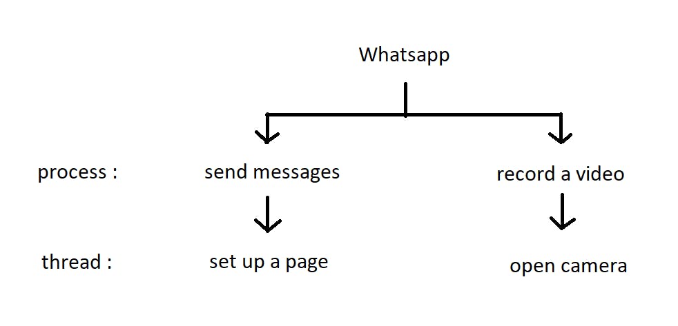
A few of the processes that Whatsapp can have are sending messages, recording videos, etc. These processes can have threads like setting up the page, opening the camera, and so on.
So, how do we send text messages on WhatsApp to our friends? It finds out the IP address and the port number on the destination device in which Whatsapp is installed.
sockets - It is a door or an endpoint that allows communication between two processes. Each process sends and receives data through its own socket. The combination of an IP address and a port number is called a socket.
Ports - There may be multiple instances of one application running (like 2 to 3 browsers opened). And there is no way to know where the data needs to go. This is where ephemeral ports come in. These ports get randomly assigned with respect to the instance of the application. Once the process gets over, it gets freed.
HTTP (Hyper Text Transfer Protocol) -
It is a client-server protocol that tells us how we request data from a web server and how the web server sends back data to a client's web browser. HTTP enables us to load web pages in our browsers and for transmitting documents such as HTML.
So whenever a client requests the server, it's called an HTTP request. When the server gives back a response, it's called an HTTP response (ex: requesting web pages). Some of the HTTP methods are GET, POST, PUT, DELETE, etc.
Every application layer protocol requires a transport layer protocol. So HTTP uses TCP to ensure all the data are sent and received successfully without any frame drop or loss of data.
HTTP is a stateless protocol. The server does not store the state of the client. So every time the same client makes a request, the server thinks of a new client making those requests every single time.
This is what an HTTP URL looks like -

Every web page is associated with a URL (Uniform resource locator). You can learn more about it on mdn web docs.
HTTP status codes - Whenever we send HTTP requests, and sometimes we don't get the required results, there should be a way to debug what went wrong. So HTTP status codes are a way we get to know whether the request was sent successfully or not. There is a list of codes that do the following tasks -
1XX (100 - 199), give useful information. (100 -continue)
2XX (200 -299), successful requests and responses. (200 - OK)
3XX (300 -399), give redirection messages. (302 -found)
4XX (400 -499), tell us about the client errors. (404 - Not found)
5XX (500 -599), tell us about the server errors. (500 - internal server error)
Cookies -
We know that HTTP requests are stateless, but this becomes a main problem when we interact with e-commerce websites, like storing products on shopping carts. So every time we log in to our account on these websites, they maintain our preferences. How does it do that? Cookies!
A cookie is a unique string, a small piece of data that is sent by the server to the client's browser when visited for the first time. This cookie stays in the browser. So, whenever the client visits the website again, the cookie is sent to the server. The server recognizes the user and maintains his/her preferences like logins, shopping carts, game scores, or anything else the server should remember.
How does HTTPS work?
HTTPS is nothing but HTTP with an extra layer of security. Hence, HTTPS stands for Hyper Text Transfer Protocol Secure. To make communications secure between a client and a web server, it introduces encryption of data so that passwords and other such user credentials can be safe while browsing through the internet, thereby ensuring data integrity.
It encrypts data using protocols such as Secure Socket Layer / Transport Layer Security (SSL/TLS). These protocols help in the encryption and decryption of data.
It secures a communication channel with an asymmetric public key architecture. There are two types of keys used for encryption:
Private key: It is used to decrypt data that has been encrypted by the public key. It is located on the server and is managed by the website's owner. It is personal in nature.
Public Key: It is public in nature and is available to all users who communicate with the server. The public key encrypts data that will be decrypted by the private key.
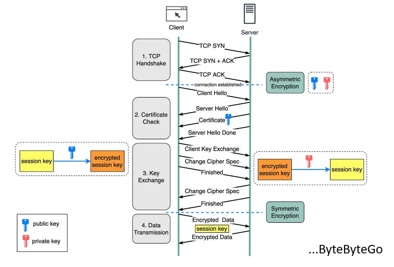
The procedure begins when a person enters a website by typing "https://" in the address bar of their browser or by clicking on a secure link. The browser requests the server, indicating its desire to create a secure connection.
The client and the server establish a TCP connection by performing a 3-way handshake (explanation ahead).
The client communicates with the server with a message. The message includes a set of required encryption techniques as well as the most recent TLS version it can support. The server responds with another message informing the browser whether the algorithms and TLS version are supported.
The SSL certificate is subsequently sent to the client by the server. The certificate includes the public key, hostname, expiry dates, and so forth. The certificate is signed by a reputable Certificate Authority (CA), ensuring that the server's public key belongs to the specified domain. The certificate is validated by the client.
The browser compares the certificate of the server to a list of trusted CAs saved on the user's device. The browser will proceed with the handshake if the certificate is authentic and trustworthy and then it will validate.
After confirming the SSL certificate, the client produces a session key and encrypts it with the public key. The server receives the encrypted session key and decrypts it using the private key.
Because both the client and the server have the same session key (symmetric encryption), the encrypted data is sent in a secure bi-directional channel.
How does email work?
For sending an email, the application layer protocol used is SMTP (Simple Mail Transfer Protocol). It uses TCP in the transport layer because no one wants to receive an incomplete email without being the sender's fault.
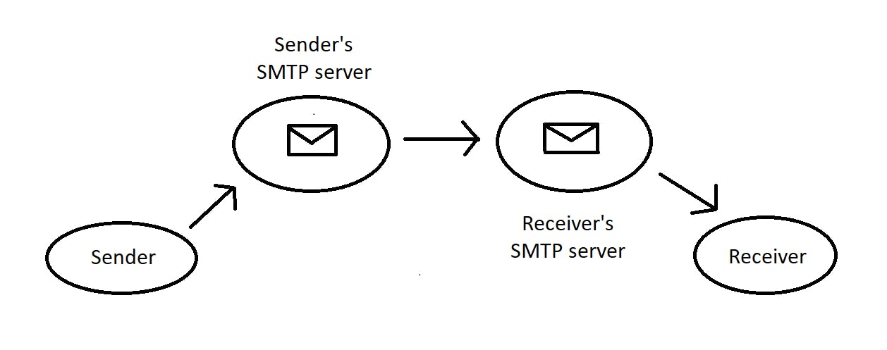
When a sender sends a mail, it gets uploaded to his SMTP server. This server establishes a connection with the receiver's SMTP server. Then it transfers all the emails to the server. The receiver downloads them from its own server using POP3 (Post Office Protocol) or IMAP (Internet Message Access Protocol).
The folders like sent items and drafts are not in sync while using POP3. Once the messages are downloaded, they are removed from the POP server. If the emails are deleted from the client, they are gone permanently.
IMAP allows us to view our emails on multiple devices. The emails stay on the server even after downloading them on the client's device.
Domain Name System (DNS) -
It acts as a phonebook/directory/database for all the existing websites around the world. It consists of all the domain names that are mapped to the IP addresses. (Thorough explanation of "What is an IP address?" coming up ahead in the Network Layer section). So, when we type "google.com", it will use the DNS to find the IP address of Google's server. These are the following steps it undergoes -
DNS lookup - When a website is visited for the first time, the browser sends a request to a DNS server to look up the IP address associated with the domain name.
First, the browser looks if the IP address is in the local cache. If not found in the local system, the browser will search for it in the local DNS server (ISP). If not in ISP, then in the root server. If not in the root server, it will ask for it in the top-level domain (TLD).
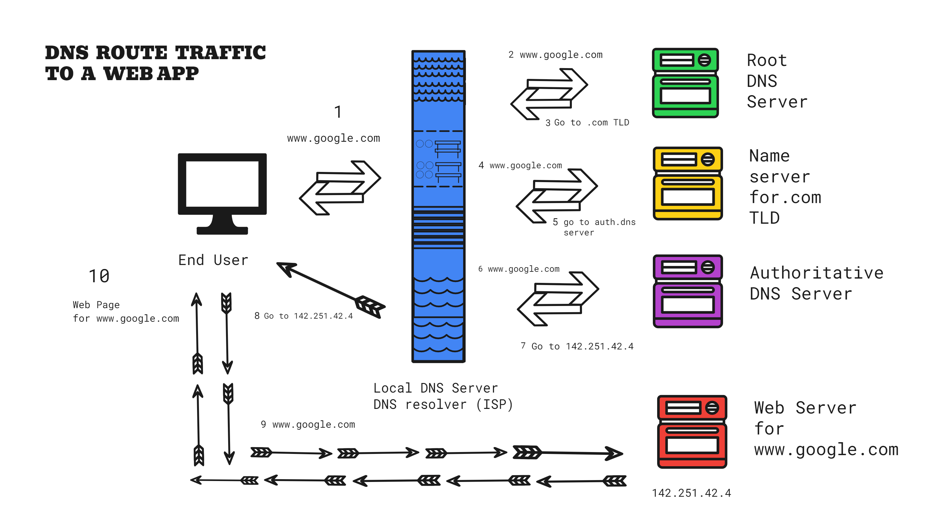
IP address retrieval - After a few recursive forwarding requests through multiple servers, the request finally gets to the authoritative DNS Name server. This server locates the IP address of the web server that is hosting our website and tells our browser to go to that address. Then the browser will store the value of the IP address it has found, in the local cache. It uses it to connect itself to the Google server to access the website.
HTTP request - The computer sends an HTTP request to the Google server asking for the homepage of the website.
Server Response - Google responds to the request with an HTML code for the homepage including texts, images, videos, music, scripts, etc.
Page rendering - The browser uses the HTML code and resources to render the Google homepage.
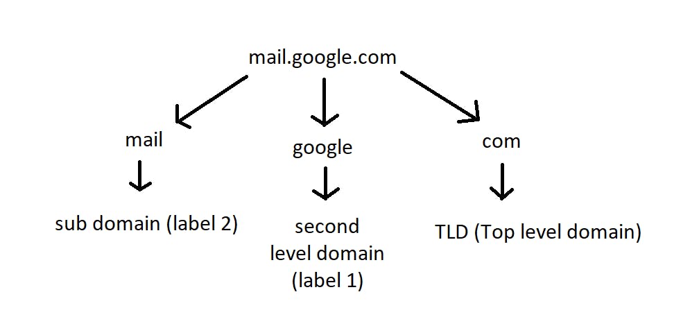
In the given image above, for the website "mail.google.com", we have three domains. It is read from right to left by the DNS servers. Instead of storing data in one database, there are multiple databases for these categories.
The " . " (pronounced as "dot") that we see over here just after "google" and before "com" is called as the root. This separates the domain names and the top-level domains.
The top-level domains are called the Root DNS servers. It is the first point of contact. The most generic TLDs (.com -> commercial, .org -> non-profit organizations, .net) do not need web services to meet any specific requirements, while certain TLDs have stricter standards in place to make it clear what their purpose is.
Local top-level domains (TLDs), such as .us, .fr, or .se, might specify that a service must be offered in a specific language or be hosted in a specific nation (canada.ca); they are meant to signify a resource in that language or nation. Only government agencies are permitted to use TLDs that end in ".gov" like "get.gov". Only educational and academic institutions may use the ".edu" TLD such as "stanford.edu". ".io" is used by startups and developers like Github.io.
The name "google" is the domain name assigned to google. And the "mail" is called the sub-domain. The sub-domains are used to further group things under "google". Various subdomains available under google are maps, mail, drive, www, apps, etc. For example, google's map service is available at maps.google.com.
The database for these root DNS servers is managed by ICANN (Internet Corporation for Assigned Names and Numbers).
We can look up the IP addresses using the "dig" and "nslookup" commands. These commands query DNS name servers to get the exact IP address of a website. If not found, these name servers recursively forward the request to other name servers until the site is found at the authoritative DNS server.
$ nslookup www.google.com
$ dig www.youtube.com
The Presentation layer
It is the 6th layer of the OSI model.
It takes the data from the application layer and converts them into machine-representable binary format (from ASCII to EBCDIC), the process is called translation.
It provides data abstraction, thereby giving the necessary information.
It provides encryption/decryption. It uses SSL protocol to encrypt data.
It uses JPEG, MPEG, JPG, PNG, and GIF to compress images so that they can sent over the network to the destination system efficiently.
It compresses data so that it can travel long distances without any frame drop or packet loss.
Hence to summarize, the presentation layer ensures that the data is properly formatted, secured, encoded, decoded, compressed, and transmitted so that it can be understood by the receiving device or application.
The Session layer
It is the 5th layer of the OSI model.
A session is a logical connection between two applications to have multiple interactions.
It helps in setting up and managing the connection (establishing session), enabling the sending and receiving of data (maintaining session) followed by the termination of connected sessions.
Before an application establishes a connection, it does authentication (asking for user credentials). then it does authorization (whether you have access to file servers or not).
It includes error checking whether the data sent and received is in sync or not.
It incorporates two modes of communication between two systems -> half-duplex (one-way communication at a time) and full-duplex (two-way communication at the same time).
The Transport layer
It is the 4th layer of the OSI model.
It transports the data we've got, to other devices we want to communicate, in segments.
The transport layer does the following tasks to ensure that the data reaches its destination.
Segmentation - Data received from the session layer is divided into smaller segments. The transport layer encapsulates data into a TCP or UDP header to form a segment. Every segment will contain a source port number, a destination port number, and a sequence number. The sequence number helps to reassemble the sequence of segments in the correct order.
Flow control - The layer manages the flow of data between the sender and the receiver to avoid congestion. For example, a server sends data at a speed of 60 Mbps and a client receives the data at a speed of 30 Mbps. Here we can see that there is a speed mismatch that won't work. This layer takes care of it.
Error control - This layer detects and transmits any lost or corrupted segments to ensure reliable delivery of data. To check whether the data is corrupted or not, it adds a checksum to every data segment.
A checksum is a value that is calculated from a block of data using an algorithm like CRC-32, MDS, SHA-1, etc.
Connection management - It uses TCP and UDP for transporting the data segments.
Let's have a brief understanding of how everything works in a transport layer..
When you text your friend over Whatsapp, the actual transportation of messages is done by the network layer. But the role of the transport layer is to take the information from the network to the application and vice versa.
The transport layer lies in the computer device. After the messages are received on the other end, the transport layer takes care of which application the messages needs to go to.
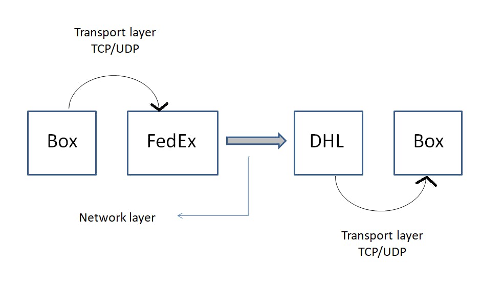
One basic analogy would be sending a package to your friend who lives in another country. Let's say you have a box you want to gift to your friend. This is the sequence it needs to go through -
The box is picked up by the courier company in your country (ex, FedEx). -> Your messages get picked up by the network layer. How does it happen? With the help of the transport layer in your device.
The courier company (FedEx) sends your box to the courier company of another country (ex, DHL Express). -> This is where the network layer takes your messages from your network and sends it to another network where your friend's device is located.
That courier company (DHL) delivers your box to your friend's doorstep. -> The transport layer in his/her device receives the messages and puts the data segments of the messages in the correct order into the Whatsapp application.
TCP takes care of it.
Now say you are sending 3 types of data (a text message, a doc. file, and a video) to your friend simultaneously to your friend. How does this data get uploaded to the network? How does the receiver end get to know which of those 3 types of data needs to go to their respective applications? This is done by multiplexing and demultiplexing.
Multiplexing - It is a technique to allow multiple signals/data bundled together to be transmitted through a single common channel.
Demultiplexing - At the receiving end, the multiplexed stream is demultiplexed to separate individual data streams and direct them to respective destinations.
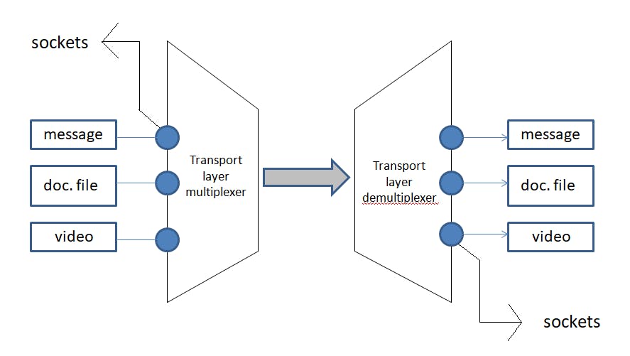
The applications with their respective data are attached to the sockets. A socket is an interface that allows programs to send and receive data while a port is used to identify which application should send or receive data.
Webpages get sent across the internet using the HTTP/HTTPS protocol over port 80 (HTTP) or port 443 (HTTPS). Emails use the SMTP protocol -> port 25, IMAP protocol -> port 143, and POP3 protocol -> port 110.
These sockets form a connection between the applications and the network. The sockets have port numbers. We know that data travels in small packets. The transport layer will receive these packets and forward them to the respective socket port numbers.
When there's a lot of data traffic, the transport layer takes care of it with the help of congestion control algorithms. These algos are built in TCP. These protocols have checksums in order to ensure that the data arrives at the destination in the correct order.
So, when you are sending some data, a checksum is calculated using that data from your side. This data along with the checksum travels to your friend. He calculates the checksum from the data he receives with the help of the same algorithm you used. Then a comparison is done between two checksums. If the values match then the data is received in the correct order as it was sent. If not, then something went wrong.
Now the question arises. How does your application know that the data you have sent is received successfully by your friend? You need to be sure that your friend has got those messages otherwise how would you engage in further conversation? For this purpose, timers do the job.
Let's have a look at case 1.
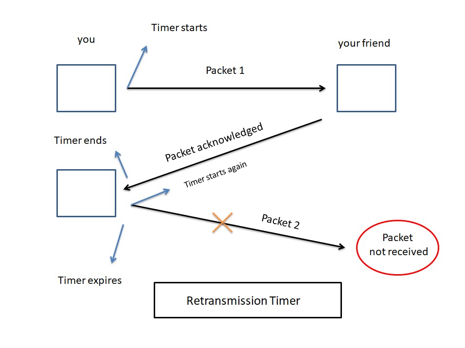
While sending messages to your friend, let's say packet 1 is transmitted by your device. At this point, a timer starts.
Once received, the other device sends an acknowledgment, telling you that packet 1 has been received successfully. Here, the timer ends.
Then you send another packet, packet 2 if you will. The timer starts again as usual.
Now you wait to receive an acknowledgment from your friend but it is taking too much time. At this point, your timer expires.
So what exactly happened? Packet 2 didn't reach your friend's device.
This is where the retransmission timer comes into play. So, once the timer gets expired, it realizes that the packet wasn't received on the other end. Hence your device will retransmit that same packet again, thereby restarting your timer.
Let's have a look at case 2.
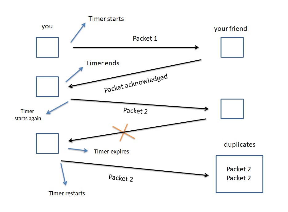
In this case, we see that packet 2 has been received by your friend.
Now he sends an acknowledgment. But due to some reason, you do not receive it. Hence your timer expires.
Since you haven't got any confirmation about the received data packet 2, your device may think that packet 2 had never reached your friend's device.
So, it starts retransmitting packet 2.
When the other device receives packet 2, it sees that there is already a duplicate of it.
Every packet is assigned a sequence number. So, your friend's device eliminates the duplicate by looking at its sequence number.
Now let's dive deeper into the protocols of the transport layer that it has to offer!
UDP -
It stands for User Datagram Protocol.
It is a connectionless protocol, meaning it does not set up a dedicated end-to-end connection. Communication is achieved by transmitting information in one direction from source to destination without verifying the readiness or state of the receiver.
It prioritizes speed over quality.
While sending data, all of it may or may not reach. There can be some loss of data on the way.
It doesn't ensure that packets are reassembled in the correct order even though it has checksums.
It is considered the fastest way of transmitting data.
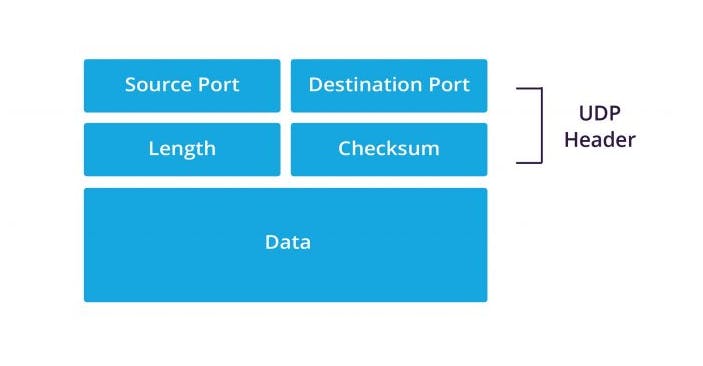
A UDP packet consists of the following -
Source port number (2 bytes)
Length of datagram (2 bytes)
Destination port number (2 bytes)
Checksum (2 bytes)
Data
The total size of the packet is 2^16 bytes = 65,536 bytes. The header contains the first four components taking a size of 8 bytes. And the data takes up space of 65,536 - 8 = 65,528 bytes.
Its use cases are -
UDP is commonly used in real-time applications such as video conferencing, voice-over IP (VoIP), online gaming, and live streaming.
DNS uses UDP as its primary protocol for DNS queries.
DHCP uses UDP for the dynamic allocation of IP addresses and network configuration parameters to devices on a network.
It offers low overhead and faster transmission compared to TCP.
To know how your data packets come in and out of your computer, run the following command -
sudo tcpdump -c 5
TCP -
It stands for Transmission Control Protocol.
It is a reliable connection-oriented protocol.
TCP establishes a connection with the destination node.
It requires a handshake between the source and the destination node.
Handshake confirms data was received. If not, then it retries.
The application layer sends a lot of raw data.
TCP segments this data and divides it into chunks, add headers, checksum, etc.
It ensures that the packets are received from the network layer and are delivered or reassembled in the correct order.
It provides congestion control and error control.
If the data doesn't reach its destination location, TCP takes care of it.
Applications for sending text messages like WhatsApp, Messenger, etc., use TCP.
For web browsing, HTTP uses TCP for sending requests to servers over the internet.
It is used by File Transfer Protocols (FTP) to send files like pdfs, documents, etc.
SMTP, POP3, and IMAP use TCP heavily to send and receive emails securely.
It is a full duplex, two computers can communicate with each other simultaneously.
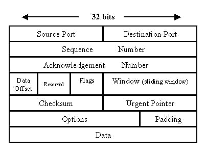
The TCP segment header looks almost the same as UDP but with some extra components like sequence number and acknowledgment number, etc.
As mentioned earlier, before sending data, TCP establishes a connection with a handshake between the client and the server. This method is called the 3-way handshake.
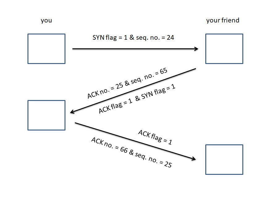
Your computer sends a SYN (Synchronization) flag = 1 along with a random sequence number (say 24).
The server sends back a SYN flag = 1, a sequence number generated at the receiver's side (say 65), and most importantly an ACK number = 25 along with the ACK flag = 1. The acknowledgment number becomes equal to the sequence number received from the sender + 1.
Now your computer sends another sequence number = 24 + 1 = 25. Also, it sends an acknowledgment number = 65 + 1 = 66, along with the ACK
flag = 1. (ACK no. ~ Sequence no. ~ Previous Sequence no. + 1)
Consider your connection established!
The Network layer
It is the 3rd layer of the OSI model.
It is responsible for the transmission of received data segments from one computer to another that is located in a different network.
In this layer, data travels in packets.
It uses the IP (Internet Protocol) for distributing data packets through the network.
This is where the routers and switches live.
Functions of the network layer -
Logical Addressing: The IP addressing done in this layer is called logical addressing. This layer assigns the sender's and the receiver's IP address to every segment and it forms an IP packet. It's in this way that every packet can reach its correct destination.
Performs routing: It moves the data packets from source to destination using the shortest path available. Some of the algorithms used are Dijkstra's algorithm, Distance Vector routing, and Link State routing.
Load balancing: This layer makes sure that the data is not overloaded over the network.
Now, how do the data packets get routed to their correct destination? Let's have a look.
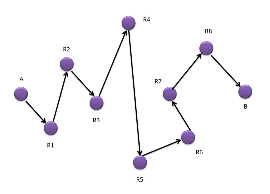
Here if we look at the given image, we have a network of routers between the source 'A' and the destination 'B' routers.
Every router device has a network address and a forwarding table. The data packet that has to travel through these many routers contains the network layer address of the source and the destination, and the information to be sent.
Now when the packet goes from A to R1. R1 checks its forwarding table for a destination address and gets to know that it needs to go to R2. Hence all these routers refer to their table to go all the way to the destination router B. This particular process is called hop-by-hop forwarding.
In the network layer, there is something called as control plane. It creates these routing tables. So in the network of routers, we can think of it as a graph. Every router acts as a node. And every link between these routers acts as an edge.
The forwarding table consists of the immediate single path to the next router. This table is a part of the routing table that contains many possible paths to the destination router.
This leads us to ask the question, which is the most suitable path to forward these packets? The shortest path! There are two types of routing -
Static routing: Routing is done manually. It is not reliable and effective as it takes too much time and effort, especially when there is a new router in the network.
Dynamic routing: It is called adaptive routing. It helps systems to adapt to network changes, learn different routes, build them in the routing tables, and then route packets through that way. It tries to create many possible routes to the destination device and chooses the shortest one. The algorithms used are BellmanFord, Dijkstra, etc.
The routers use some protocols to route data packets efficiently to the destination address. These protocols define how to route the packets by choosing the best and the shortest possible path. The protocols are -
Interior gateway protocols such as Routing Internet Protocol (RIP) and Open Shortest Path First protocol (OSPF). These protocols route packets of information within an autonomous system.
Exterior gateway protocol such as Border Gateway Protocol (BGP). This protocol routes data packets between two autonomous systems.
Internet Protocol (IP) -
- IPv4 -
This is the most commonly used Internet protocol being the fourth version.
It uses a 32-bit address containing 4 words. The unique IP addresses assigned by this protocol is 2^32 which is roughly 4.3 billion IP addresses. These addresses are running out as people are using more devices.
An IP address has two components, a network address, and a host address. The host address identifies the device within the network. The network address identifies the network to which the host belongs.
Each word is an 8-bit octet that is represented by a decimal value. There are 4 words in an IPv4 IP address separated by a dot, hence being a 32-bit address.
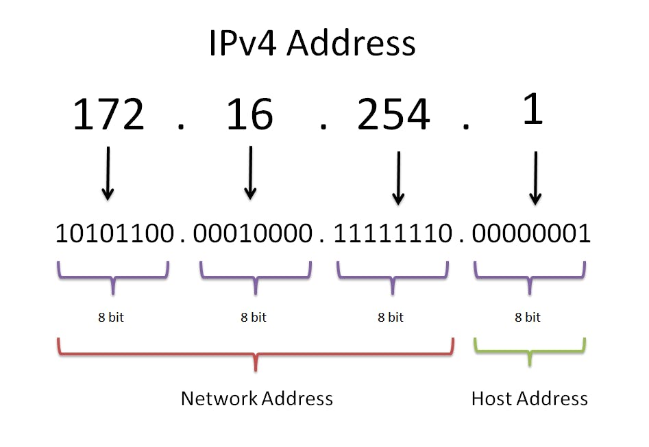
In the given image, the first three words denote the network address (reading from the left) and the last one is the host address.
Note: The division between the network address and the host address is determined by the default subnet mask associated with the address class.
A block of IP addresses is mentioned in the packets that hop over various Internet service providers (not our routers).
Classes of IP addresses - There are a total of 5 classes of IP addresses A, B, C, D, and E. The range of these classes are -
Class A : 0.0.0.0 - 127.255.255.255
Class B : 128.0.0.0 - 191.255.255.255
Class C : 192.0.0.0 - 223.255.255.255
Class D : 224.0.0.0 - 239.255.255.255
Class E : 240.0.0.0 - 255.255.255.255
Subnets - A bigger network when divided into smaller networks, is called a subnetwork or a subnet.
A subnet is a group of hosts with IP addresses that are similar in some way.
These hosts are usually in a proximate location from each other and can easily send data to and from hosts on the same subnet.
For example, all hosts with an IP address that starts with 123.32.45 would be on the same subnet. Let's say we want to send an email to John. If we are on the same network, our host would have an IP of 123.32.45.8 and John would have an IP of 123.32.45.9.
The common numbers are our network prefixes and 8 and 9 are our hosts, therefore our network is the same as John's.
A subnet is divided into a network prefix, such as 123.45.67.0 and a subnet mask.
Subnet masking - A subnet mask is a 32-bit number created by setting host bits to all 0s and setting the network bits to all 1s. In this way, the subnet mask separates the IP address into the network and host addresses. The default subnet masks for various classes are -
Class A : 255.0.0.0
Here, 255 (the first octet) denotes the network and the last three octets are the host addresses. These are intended for larger networks.
Class B : 255.255.0.0
Here, 255.255 (the first two octets/words) denotes the network and the last two octets are the host addresses. These are intended for medium-sized networks.
Class C : 255.255.255.0
These are intended for smaller networks.
For example, the first three octets of a class C address are used to describe the network. The 192.168.0 element of the address "192.168.0.15" describes the network, while the 15 piece describes the host.
Each network has only one subnet by default, which contains all of the host addresses defined therein. A netmask is a specification of the number of address bits used for the network part. A subnet mask is another netmask used within the network to further split it.
Each address bit that is important for describing the network should be represented by a "1" in the netmask.
For example, the above-mentioned address, 192.168.0.15, can be stated in binary as 1100 0000 - 1010 1000 - 0000 0000 - 0000 1111.
As already mentioned, the network part of class C addresses is the first three octets or the first 24 bits. Since we wish to save these significant bits, the netmask would be 1111 1111 - 1111 1111 - 1111 1111 - 0000 0000.
Variable length subnets - Variable Length Subnet Mask (VLSM) is an IP network design approach for creating subnets with varying subnet masks.
CIDR or Classless inter-domain routing is used to represent a subnet mask more properly. A subnet such as the 10.42.3.0/255.255.255.0 is written as 10.42.3.0/24 which means it includes the subnet prefix and the subnet mask.
Number of host addresses = 2^(32 - subnet mask) - 2. '2' is subtracted because we have to account for the network address and the broadcast address.
The network address represents the beginning of an IP subnet. It is used to identify the network itself. If a device has an IP subnet of 192.168.1.0/24, the network address is 192.168.1.0
The broadcast address is the last or the highest in an IP subnet. It is used to broadcast messages to all devices within that subnet. For example, in the subnet of 192.168.1.0/24, the broadcast address is 192.168.1.255
If we have a subnet mask of 12.0.0.0/31. Here "31" represents that the first 31 bits are network reserved. Since an IP address is 32 bits. It can assign only 2^1 IP host addresses. Here no. of host addresses = 2^(32-31) = 2^1 = 2 addresses. This leaves us with only a network address and a broadcast address.
Similarly, for a subnet mask of 192.0.1.0/24. The first "24" bits are reserved for the network, and the remaining 8 bits are for hosts. Here no. of host addresses = 2^(32-24) - 2 = 2^8 - 2 = 256 - 2 = 254 addresses. Here the network address is 192.0.1.0 and the broadcast address is 192.0.1.255, giving a range of usable host addresses from 192.0.1.1 to 192.0.1.254.
Subnet masks are used in order to improve security and performance. allocate IP addresses more efficiently, etc.
There are reserved addresses too. For example, 127.0.0.0/8, the first 8 bits are reserved, the rest can be anything. In localhost, the IP address of a local computer is 127.0.0.1, it's called the loopback address. This IP address allows the computer to connect and communicate with itself. The computer essentially becomes the server and client at the same time.
The IPv4 packets consist of a header (20 bytes) and a payload where data resides. The header contains the IP version, length, ID no., flags, protocols, checksums, source & destination addresses, TTL (Time to live), etc.
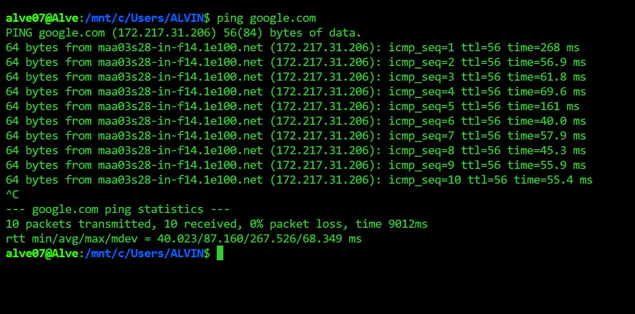
We can type the following command to know how the data packets are received from a particular server.
ping google.com
- IPv6 -
IPv6, the most recent version of the Internet Protocol, was established to solve the shortcomings of the IPv4 protocol.
IPv4's 32-bit addresses allow for a maximum of 4.3 billion distinct addresses. In contrast, IPv6 employs 128-bit addresses, allowing for a much bigger number of unique addresses, 2^128 = 3.4 x 10^38, i.e., 340 undecillion IP addresses! This is significant because IPv4 addresses are running out and the number of devices requiring internet connection is growing.
Furthermore, IPv6 provides additional security features such as integrated authentication and encryption, as well as improved compatibility for mobile devices.
IPv6 support is becoming more widespread among websites and internet service providers, and it is expected to progressively replace IPv4 as the primary internet protocol.
An IPv6 address consists of eight groups of four hexadecimal digits. Here’s an example IPv6 address, 3001 : 0da8 : 75a3 : 0000 : 0000 : 8a2e : 0370 : 7334.
some advantages are -
It is highly reliable.
Multicast is supported by IPv6 as opposed to broadcast in IPv4.This function enables the simultaneous transmission of packet flows with high bandwidth requirements, such as multimedia streams.
IPv6 includes IPSecurity, which offers data integrity and secrecy.
some disadvantages are -
IPv4 and IPv6 machines cannot communicate directly with each other. The device that is configured with IPv4 can't access the websites configured with IPv6.
It will take some time to shift to IPv6 due to generalized use of IPv4 and also it will take a lot of hard work.
The Datalink layer
It is the 2nd layer of the OSI model.
The data unit in this layer is called a frame.
This layer receives the data packets from the network layer (at the sender's end) and divides them into frames providing node-to-node delivery over the physical layer bit-by-bit.
It performs physical addressing. Meaning, the data link layer encodes the source and destination's MAC address/physical address in the header of each frame. The MAC address (12-digit alphanumeric number) is the unique hardware address or the physical address assigned to the device during manufacturing.
Every system that wants to get connected to the internet gets a device called the network interface card (NIC).
This NIC is assigned a hardware address called the MAC address that is used to identify the machine on a network and is embedded into the NIC's firmware.
A MAC address for an ethernet device looks like this -> 00:C4:B5:45:B2:43
DLL inserts error detection bits into the frame's header, allowing the receiver to determine if the data received is accurate or not.
It helps to synchronize the data flow speed between the sender and the receiver such that the rate of flow of data remains constant on both sides.
It is possible that many devices may communicate using a single channel giving way to the collision of data. Hence, this layer checks which device has access to the channel to prevent collision and loss of frames.
For this purpose, this layer uses the protocols CSMA/CA (Carrier Sense Multiple Access with Collision Avoidance) and CSMA/CD (Carrier Sense Multiple Access with Collision Detection).
There are two sublayers -
Logical Link Control (LLC) layer: The topmost sublayer, LLC, multiplexes protocols operating at the data link layer's top and optionally supports flow control, acknowledgment, and error notification.
Media Access Control (MAC) layer: The word "MAC" may refer to the sublayer (such as CSMA/CD) that controls who is permitted to access the media at any given time. It may also refer to a frame structure that is transmitted based on the MAC addresses included within.
There can be many devices connected in a LAN. And each of them has their respective MAC address. Suppose device 1 wants to send data to device 3. It will check in its cache whether it has the MAC address of device 3 using ARP (Address Resolution Protocol). Only then it will proceed.
ARP is used to find MAC address associated with a known IP address. It is used within the same local network.
Let's say, device A wants to communicate with device B. Device A will first use its ARP look up table to check if it can find Device B's MAC address based on its IP address. If not, it will use the ARP procedure.
Device A will send a broadcast message to all the hosts on a network using ARP to find out which host has the requested IP address.
Any machine with the requested IP address will reply with an ARP packet containing the IP address and the MAC address.
Now that device A has the IP and MAC addresses of Device B encapsulated in a frame, the data link layer of Device A will send the frame through the network interface card passed on to the physical layer.
The Physical layer
It is the bottommost 1st layer of the OSI model.
This is where the hardware components lie like power plugs, connectors, receivers, cables, hubs, ethernet, etc.
It includes a crucial feature known as modulation, which is the technique of transforming data into radio waves by adding information to an electrical or optical nerve signal.
The data rate (how many bits a sender can transfer per second) is maintained by the Physical Layer.
It achieves bit synchronization.
It aids in the selection of the Transmission Medium (the direction of data flow).
It aids in the selection of Physical Topology (Mesh, Star, Bus, Ring) (Topology used to connect devices).
The mode of the transmission medium can be simplex, half-duplex, and full-duplex.
Simplex is where one device can transmit data, while the other device can only receive it, (ex..tv and radio broadcast).
Half-duplex is where two devices can communicate with each other but one at a time, (ex..walkie-talkie).
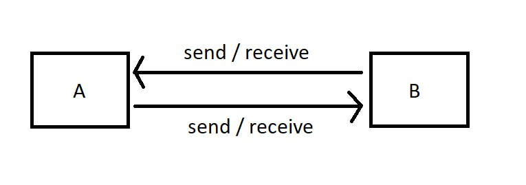
Full-duplex is where both can send and receive data at the same time like texting applications, telephonic systems, video calls, etc.
Networking tools
ping: This command is used to check whether a required host is reachable or not by sending ICMP echo messages and expecting ICMP reply messages in return from the host. (ICMP - Internet Control Message Protocol)
ping www.google.comtraceroute: It is used to see how a packet is being routed throughout the internet and measure transit delays of packets across an Internet Protocol Network. It identifies the path taken by the packet from the source to the destination showing each intermediate hop and time taken to reach that hop. Each packet gets a certain time to live called TTL (Time To Live) because we don't want our packets to revolve around the internet in case it doesn't get to the destination host.
traceroute google.comnetstat: It displays various network-related information such as network connections, running processes, routing tables, information about network interfaces, details about open ports, listening and non-listening sockets for network connections, and much more. It is basically the Swiss army knife of networking tools.
netstat -aTo check different ports that are in use, run..
netstat -tulnpnmap: This command discovers hosts and services on a computer network. It is used to assess the security of networks and check for any vulnerabilities. It maps networks.
nmap 172.217.27.174tcpdump: It captures packet data and analyzes traffic on a network in real-time.
tcpdump -i wlan0ifconfig: It allows us to configure and display network interfaces. The most commonly known interfaces are eth0 (First Internet Card on the machine), wlan0 (wireless interfaces), lo (loopback interface), etc. These network interfaces allow the kernel device drivers to communicate with the network.
ifconfig -anslookup: Querying DNS name servers for domain information and resource records.
nsloopkup google.comdig: short for Domain Information Groper, queries DNS name servers to resolve domain names to IP host addresses, thereby obtaining information about domain names, IP addresses, and DNS records. It is more flexible than nslookup and great for troubleshooting DNS issues.
dig www.google.comWireshark: It is a packet analyzer that is great for network troubleshooting and analysis of interactions or communication between various network components. It captures packet activity in a network and analyzes it.
iperf: It assesses data transfer speed between two systems by generating TCP and UDP traffic. It measures the bandwidth and performance of a network.
# On the server side
iperf -s

# On the client side
iperf -c <server_ip_address>
Outro
In today's interconnected world, understanding computer networks is critical. Computer networks serve as the foundation of modern communication, facilitating information sharing and enabling the operation of numerous services and applications. Individuals and organizations may leverage the power of technology more efficiently and make educated decisions regarding network design, configuration, and security by understanding the underlying concepts and principles of computer networks.
Any suggestions and improvements for this blog are most welcome.
References
https://www.youtube.com/watch?v=IPvYjXCsTg8&list=PL9gnSGHSqcnoqBXdMwUTRod4Gi3eac2Ak&index=3
https://www.geeksforgeeks.org/physical-layer-in-osi-model/?ref=gcse
https://www.ionos.com/digitalguide/server/know-how/what-is-arp-address-resolution-in-networks/
https://www.ionos.com/digitalguide/server/know-how/data-link-layer/
https://www.geeksforgeeks.org/introduction-of-variable-length-subnet-mask-vlsm/
https://www.meridianoutpost.com/resources/articles/IP-classes.php